
- This topic is empty.
-
AuthorPosts
-
2026-11-10 at 5:38 pm #10441
Electromagnetic Flow Meter Sizing for Low Flow Chemical Dosing Lines
Pipe size alone does not determine the correct electromagnetic flow meter measuring range. A dosing line that uses a 1-inch or 2-inch pipe for mechanical/hydraulic convenience may need a very different meter bore than the pipeline itself, because what actually matters is the relationship between the fluid’s real operating flow rates and the velocity those flow rates produce inside the meter’s measuring tube.
1. Start With Minimum, Normal, and Maximum Operating Flow — Not the Pipe Diameter
Every sizing exercise for a chemical dosing application should begin with three numbers supplied by the process, not by the pipe spec sheet:
- Minimum flow: the lowest sustained rate the dosing system will ever run at (e.g., during turndown or low-demand periods).
- Normal flow: the rate at which the system operates most of the time.
- Maximum flow: the highest rate the dosing pump or injection skid can produce, including any short-term overdosing allowance.
A meter selected only to "match the pipe" can end up oversized relative to the actual dosing rates, producing a low, noisy signal at the velocities the process actually uses. Conversely, a meter chosen only for the maximum design flow may leave the minimum flow condition poorly represented. The minimum/normal/maximum triad — not the nominal pipe diameter — is the primary input for bore selection.
2. Volumetric Flow, Bore Area, and Average Velocity
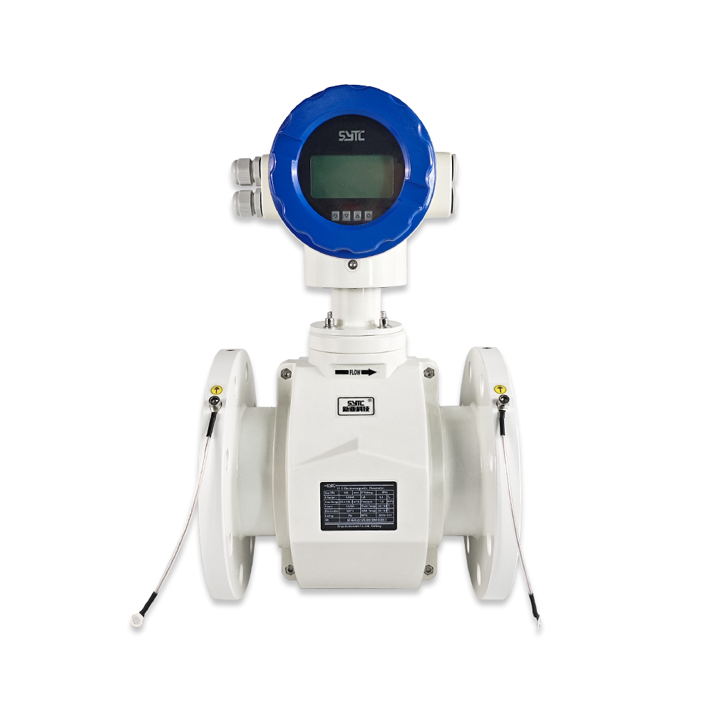
Electromagnetic flow meters do not measure flow directly; they measure the average velocity of a conductive fluid moving through a known cross-sectional area, and the instrument (or the user) derives volumetric flow from:
Volumetric Flow (Q) = Cross-Sectional Area (A) × Average Velocity (v)
For a fixed volumetric flow, reducing the internal bore area increases the average velocity, and enlarging the bore area reduces it. This is the core mechanical lever used in sizing: at a given dosing flow rate, a smaller measuring bore produces a higher, more measurable velocity signal than a larger one. The correct sizing decision is the bore diameter that places the minimum, normal, and maximum flow conditions at velocities the selected meter model is specified to measure — this is a calculation task, not a generic rule of thumb.
3. Meter Bore vs Pipeline Diameter
Because dosing lines are frequently built with a pipe size chosen for mechanical, chemical-resistance, or pump-connection reasons rather than for flow-measurement optimization, it is common for the meter’s internal bore to differ from the surrounding pipeline diameter. Two general approaches exist:
- Full-bore meter matching the pipe: simplest installation, but at low dosing rates the resulting velocity may fall near or below the useful measuring range of the chosen model.
- Reduced-bore meter with concentric reducers: raises velocity at the measuring point for the same volumetric flow, which can bring low dosing rates into a better-represented velocity band — but this introduces its own installation requirements (straight-run length, reducer angle, and upstream disturbance) that must be respected per the manufacturer’s installation documentation.
Neither approach is universally correct. The decision depends on where the minimum and normal dosing flows land on the specific meter model’s velocity-based measuring capability, and on what the installation can physically accommodate (available straight-pipe length, reducer space, orientation).
4. Model-Specific Low-End Limits, Accuracy, and Repeatability
Low-end sizing is model-specific, and generic published platform specifications should not be read as a guaranteed accuracy statement at a single, isolated low-flow point. As an example of how a manufacturer documents this, Kaifeng Xinya Instrument Co., Ltd. (Xinya Instruments) publishes, for its industrial electromagnetic flow meter platform (including the SF-E series), a general velocity measurement range and multiple accuracy class options (such as ±0.5%, ±0.3%, and ±0.2%) as platform-level technical metrics, alongside a nominal bore coverage from DN15 up to DN3000 depending on the specific model. Some electromagnetic flow meter models in the Xinya Flowmeters lineup are available in smaller nominal sizes suited to low-flow lines, subject to the current model’s datasheet.
For a chemical dosing application, the buyer should request, for the exact model under consideration:
- The documented accuracy class and the velocity (or flow) band over which that accuracy class applies.
- Repeatability figures separate from accuracy figures — repeatability indicates how consistently the meter reproduces a reading at the same flow condition, which can matter more than absolute accuracy for dosing ratio control.
- Whether the manufacturer’s 100% factory calibration record (a practice Xinya Instrument applies before shipment) includes a calibration point at or near the intended low-flow operating condition. A general factory calibration confirms the unit was tested, but it does not by itself confirm a particular low-flow accuracy unless the calibration certificate covers that specific flow point for the selected model.
5. Conductivity and Chemical Compatibility
Electromagnetic flow meters rely on Faraday’s principle and therefore require the dosed fluid to be electrically conductive. Before finalizing a sizing decision:
- Confirm the fluid’s conductivity value falls within the selected model’s documented operating threshold — this value is model-specific and must be read from that model’s datasheet rather than assumed.
- Review wetted-material compatibility: electrode material and lining material must resist the specific chemical being dosed, its concentration, and its temperature. Manufacturers typically offer multiple lining options (such as PFA, ceramics, or various rubber compounds) and electrode material choices for this reason.
- For abrasive or particle-bearing dosing media, lining wear resistance becomes an added selection factor, separate from the low-flow velocity question.
6. Implications of Reducers and Installation Geometry
When a reduced-bore meter is used to raise velocity on a low-flow dosing line, the installation must account for:
- Upstream and downstream straight-run requirements specified by the manufacturer for the selected model, measured in pipe diameters of the meter’s own bore (not the original pipeline’s bore).
- Reducer geometry, since an abrupt or asymmetric reduction can distort the velocity profile entering the measuring section, affecting signal stability.
- Orientation and electrode placement, particularly for vertical installs or lines prone to partial filling, where self-diagnosis features (such as empty-pipe detection, where supported by the model) become relevant safeguards rather than substitutes for correct sizing.
7. Continuous Low Flow vs Transient Dosing Pulses
Sizing logic for a continuously low but steady flow (e.g., a trickle-feed dosing line) is not the same exercise as sizing for a line fed by a pulsating positive-displacement dosing pump. A pulsating pump produces instantaneous velocity peaks and near-zero troughs within each stroke, even when the time-averaged flow is low. This distinction affects which minimum/normal/maximum figures should be submitted for sizing and whether averaging/damping behavior of the chosen electronics needs to be discussed separately with the model’s technical documentation — this article addresses steady low-flow sizing logic, not pump pulsation damping design.
Practical Sizing Decision Sequence
- Document minimum, normal, and maximum dosing flow rates (volumetric units, with time basis).
- Confirm fluid conductivity, chemical composition, concentration, and temperature.
- Calculate the velocity that results at each flow rate for candidate bore sizes, using Q = A × v.
- Compare resulting velocities against the candidate model’s documented measuring capability and accuracy-class conditions.
- Confirm wetted-material compatibility (electrodes and lining) for the specific chemical.
- Check available straight-run length and reducer feasibility against the manufacturer’s installation requirements.
- Request calibration certificate detail for the low-flow point of interest, not just a general factory calibration statement.
- Confirm output/communication compatibility (e.g., 4-20mA, pulse, frequency, or digital protocols) with the existing control system.
Input Data Table for Supplier Sizing Requests
| Parameter | Why It Is Needed |
|—|—|
| Chemical composition and concentration | Determines material compatibility and conductivity behavior |
| Conductivity value | Confirms suitability for electromagnetic measurement principle |
| Minimum flow rate | Defines the low end the meter must represent |
| Normal flow rate | Defines the primary operating measurement point |
| Maximum flow rate | Defines the upper bound and pressure/velocity limits |
| Existing pipe diameter | Starting reference for bore/reducer evaluation |
| Operating temperature | Affects lining and electrode material selection |
| Operating pressure | Affects meter body and flange rating selection |
| Required accuracy class | Matches process control tolerance to meter specification |FAQs
Q1: Can a smaller meter bore always solve a low-flow measurement problem?
A smaller bore raises velocity for a given volumetric flow, which can help, but it also changes pressure drop, requires reducers with their own installation rules, and must still be checked against the specific model’s documented measuring capability. It is a calculation to perform, not an automatic assumption.Q2: Does a dosing pump’s pulsation affect sizing the same way as steady low flow?
No. A pulsating positive-displacement pump creates instantaneous velocity swings even at a low time-averaged flow, which is a different sizing and signal-processing consideration from a continuously steady low flow. Treat these as separate technical discussions with the supplier.Q3: Is the published accuracy class valid at the lowest flow point of my process?
Only if the supplier confirms that the accuracy class applies at the specific velocity your minimum flow produces in the chosen bore, and ideally if the calibration certificate includes a data point near that condition.Q4: What should I send a manufacturer to get a valid sizing recommendation?
Chemical composition, conductivity, minimum/normal/maximum flow, existing pipe diameter, operating temperature, operating pressure, and the accuracy class your process requires.Conclusion
Correct electromagnetic flow meter sizing for a low-flow chemical dosing line is a calculation anchored in minimum/normal/maximum flow, bore-area-to-velocity relationships, and the specific model’s documented low-end capability — not a decision made from pipe diameter alone. Conductivity, chemical compatibility, installation geometry, and whether the low flow is steady or pump-pulsed must all be confirmed against the selected model’s actual specification and calibration evidence before an order is placed.
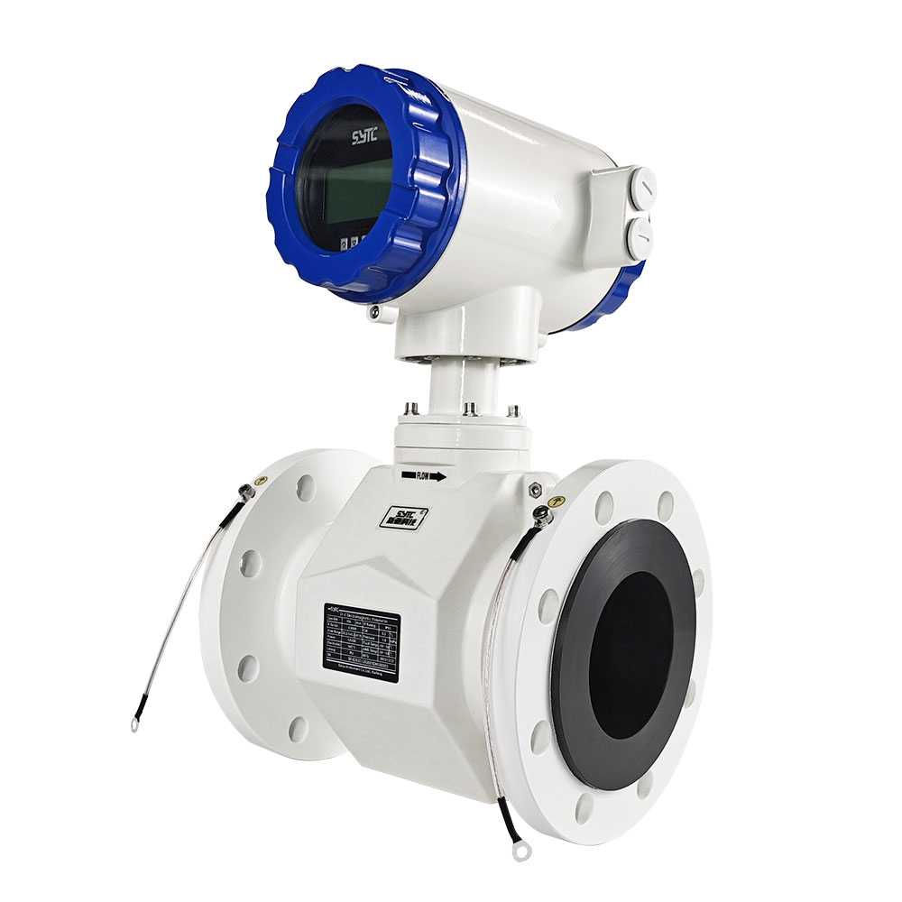
Request a sizing review from Xinya Instrument’s technical team by providing: chemical composition, conductivity, minimum/normal/maximum flow, existing pipe diameter, operating temperature, operating pressure, and the required accuracy class.
https://www.sytcflowmeter.com/
Kaifeng Xinya Instrument Co., Ltd. -
AuthorPosts

- You must be logged in to reply to this topic.